GROUPGRAVITY
We build audio and control infrastructure, for interactive performances and installations of many different kinds. Interdisciplinary projects led into collaborations with musicians, circus artists, vj´s and dancers (find selected performances here)
Our software translates any “motion” in real-time into data for controlling sound, light, video, etc.
The system is driven by live-video, the performers are not connected to any wires, sensors, etc.. The program is written in C++ and direct sound and works with minimum latency (already back in 2001, when we came up with it).
The core of our software, which we call „LiveBuilder“ is a real time video motion capture and position tracking software (“VMS unit”).
The software was programmed by Christian Vogel under C++ and developed by GroupGravity
until the tragic death of Christian.
The VMS unit is able to control audio and video in a lot of different ways.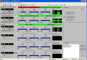
•) First of all, LiveBuilder integrates an “extended” sound/music player which is placed in the main window (Figure 1).
It can handle 6 sound banks which can be loaded with an unlimited amount of soundfiles. They can be played simultaneously and each sound can be configured with a VST plugin.
Sound output is based on Steinbergs ASIO interface to achieve best sound quality and minimum latency.
All sound controls (volume, pitch, panorama and VST plugin parameters) can be controlled and connected to the VMS unit.
•) Additionally all motion and position data (calculated by the VMS unit) can be sent via MIDI to other devices or applications.
This makes it possible to control VJ programs or other applications that respond on MIDI events.
•) Because of the capability of controlling VST plugins also virtual VST and MIDI instruments can be controlled by the VMS unit.
1) The VMS (Video Motion Sensor) unit
The unit uses any video input device as input (webcam, video camera or camcorder) and controls any parameter of sound or video output.
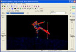
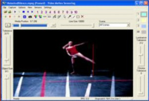
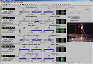
Figure 3 shows the VMS window.
On the one hand the VMS window displays the video input, on the other hand virtual lines and fields can be defined that should control sound or video output.
A simple vector drawing program is integrated to define easily the lines and fields that should control the sound or video.
Lines can be used to play, stop and switch between sounds. E.g.: a dancer touches a line and a sound starts to play which is show in Figure 3 and 4.
If the VMS unit is connected to a VJ program, e.g.: the lines can be used to play, pause or stop a video.
Furthermore audio and video output can be synchronized.
Fields can be used to control volume, pitch, panorama or VST plugin parameters of a sound. E.g.: small/no motion within a field results in a soft sound, fast motion will result in loud sound.
If the VMS unit is connected to a VJ program, e.g.: the intensity of motion can control the speed or position of a video.
The VMS unit supports various modes of position tracking and movement sensoring.
1.1) Motion capture mode
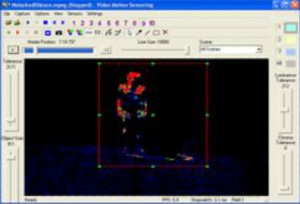
In this mode VMS reacts on movements in the view of the camera. Each frame (picture) is compared with its preceding one.
The amount of change between two frames is calculated and is interpreted as the “amount of the movement”.
1.2) Difference capture mode
Difference capture mode is similar to motion capture mode.
At first a reference picture is taken by the camera.
This is usually the basic or mean position of a person or an object.
After that, each frame is compared with this reference picture.
The further the frame differs from the reference picture the bigger is the response of the VMS unit.
1.3) Colour capture mode
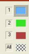
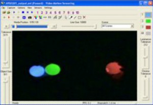
In colour capture mode the VMS unit only reacts on specific colours. These colours can be defined in the VMS window by a normal colour dropper tool .
Currently 3 different colours are supported: The VMS unit compares every pixel with the defined colours.
If the colour of the pixel is within a defined colour tolerance region, the pixel is included in the calculation of the VMS unit.
Otherwise the pixel is ignored and has no influence in the calculation.
1.4) Combination of motion/difference and color capture mode
These modes are equal to motion and difference capture mode (described in 1.1 and 1.2).
The only difference consists in that only objects are recognized that are similar (within a defined color tolerance region) of the selected color.
That means at the example of the juggling balls: if “Color 1” (blue) is selected, only motions of the blue juggling ball will be recognized by the VMS unit and will take effect on audio or video.

